For the last three months I have been teaching an intensive, twenty-hours-a-week class for underprivileged adult students in CAD design with Solidworks and Fusion 360, and metalwork starting with manual milling machines and working up to modern HAAS CNC machines. I first gained these skills by self-teaching myself at makerspaces like Techshop and Autodesk Pier 9, and consider these skills amongst the most empowering abilities to a designer or person with creative ambitions, so I was excited to share my enthusiasm with the students. But it was also incredibly daunting- this was an incredibly ambitious undertaking. Many of my students had not previously had any experience with metal work or machining, and a normal course covering the breadth of topics I set out to, budgets a year or more for all this. However, all of the students were interested and motivated, so I took them on a whirlwind tour over the 12 week class. At the end of the class, each student had designed and manufactured their own part, start to finish: from creating their own 3d CAD drawings, to setting up the machines, generating toolpaths, and correctly setting work and tool offsets and speeds and feeds. 100% of my students achieved their HAAS basic CNC mill operator certification, too. Over the next few weeks I’ll be collecting my reflections about the course in this post with frequent updates, especially attempting to explain in the right words: What worked well, and what didn’t, in this experience?
Amphibious Bicycle Construction Prep: Scanning the Hull
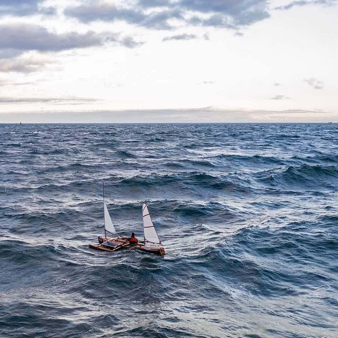
I’ve been having some powerful dreams of building a custom bicycle for bicycle touring adventures such as I’ve enjoyed a few times before— but this time, I want to incorporate a few really novel elements into the design, so that the resulting vehicle can effectively meet the serious(!) challenges (and experience the opportunities) of both the all-terrain amphibious Kinetic Sculpture Race (KSR), and the at-times brutal Race to Alaska – a 750 mile coastal boat race up the entire length of British Columbia, in the wild Pacific ocean, with one rule: no motors. So: what I’ll build will not look exactly like a typical bicycle, but it will function like one- as well as a (fast? fast.) and seaworthy small sailboat.
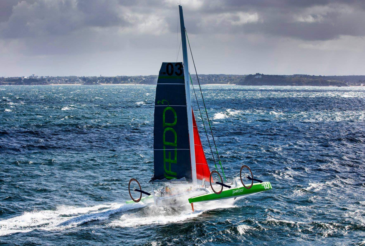
Whatever I build will need to be able to traverse steep and soft sand-dunes, rocky river shores, roll along miles-long coastal beaches, pedal easily over 50+ miles of paved roads, or, in the Race to Alaska, weather incredibly challenging conditions including steep waves and at times gale-force winds in the north Pacific. (Several boats in the 2019 R2AK snapped centerboards off, and broke rudders, due to the violence of the conditions encountered at the start of the epic 2019 R2AK).
Can I design, fabricate, and pilot a very-seaworthy bicycle/watercraft through all these conditions? I think so, and I’ll share here my progress towards this objective.
COVID IMPACTING GCKSR and R2AK
Unfortunately, because of the pandemic, both of my best motivating deadlines, the Kinetic Sculpture Race and the Race to Alaska, have been called off due to concerns of contagion and the closed international borders with Canada, respectively. But, there is an online group of weird bicycle-building creative souls, called “FreakBikers Unite!“, which is conveniently having a build-a-thon, internationally via the internet, and so this will be the framing and helpful-deadline to keep this project motivated. (To be honest my goals are beyond any of these events, but they each provide unique framing and motivation). The rules of the so called “LOLBO” or “Laugh out Loud Build Off”, are that it must be Rideable, and it must make people laugh. (No mention of Amphibious there, but it’s not ruled out, certainly). (More on why this will make people laugh, and what art it is/carries during the Kinetic Sculpture Race, later.)
The remainder of these posts will be at times highly technical, as I need to teach myself (I get to teach myself) a lot of new skills to pull off what I have in mind- but I’ll try to come up for air from time to time and put all the technicalities into context, if you bear with me. Skills like working with composite materials (fiberglass, carbon fiber) and figuring out the boat-builder tricks of how to efficiently work with the curvy shapes that water flows most kindly over. (As a rule, boats are nowhere flat or square, and so designing and building them takes some real out-of-the-box thinking compared to most other branch of engineering). Molding, in particular, is going to be something I’ll get much more familiar with over this project.
CHALLENGE #1
MEASURE THE DONOR KAYAK:
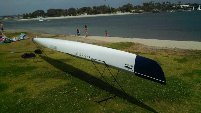
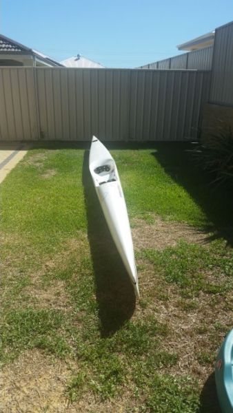
I’m going to be building upon a donor kayak, thus saving myself incalculable hours sanding and fairing. The donor kayak I found is pretty spiffy, too- a Fenn “Millenium”. At 21′ long and only 17″ at it’s widest, and with a wave-piercing axe bow, it’s quite easy on the eyes, and the water. (A friend who used to professionally race sea kayaks said it was among the fastest kayaks in the world). The length-to-beam ratio is 14(!): just slightly broader than a needle in the water. And the thing is incredibly light – it’s built of carbon fiber, and weighs maybe 35 pounds, all 21 feet of it. It won’t stay that weight for long, as I repair and add to it, but it’s a good start.
Before you go assume I’m either Mr. Moneybags (I think these things sell new for on the order of $2k) or Mr. Incredibly Wasteful (ie. how dare he cut into a perfectly good kayak!), let me mention that I saved this kayak from the trash heap; It blew off a vehicle and has two big cracks, like beltlines, running around the hull. Its previous owner was happy to drive it to me in exchange for gas money and a steak lunch.
Before I describe what I’m going to add to it, and how, and why, I need to measure what I have already:
STEP 1: 3D SCAN THE HULL
(STEP 1.1: BUILD A 3D SCANNER)
Given that I want to leverage digital fabrication techniques like CAD, CAM, and CNC tools like 3d printing and CNC milling/routing, I really need accurate geometry for what I’m starting with. Also, since repairing the hull will require me to cut the top off the kayak, there’s a risk it could fall out of shape, since it’ll then be quite flexible. So I need to make an accurate cradle to support the hull while it’s weakened. To make this cradle, as well as model accurate additions to the hull (which I’ll get into later), I need to measure the shape of the hull very accurately. But boats are nowhere flat or square, so how do you measure the 3D shape of a boat to make an intimately fitting cradle for it along it’s whole length? For starters, having a support every foot or so along the length will be sufficient. I only need to make 20 or so frames to cradle the hull in cross section, every foot or so. There’s many ways this could be done (“ticking stick” template making, or bending a lead bar around it which is then removed and traced, were two considered options) but I ultimately decided to leverage my extensive collection of robotics gizmos like linear slides, bearings and shafts, and highly accurate angle-encoders.
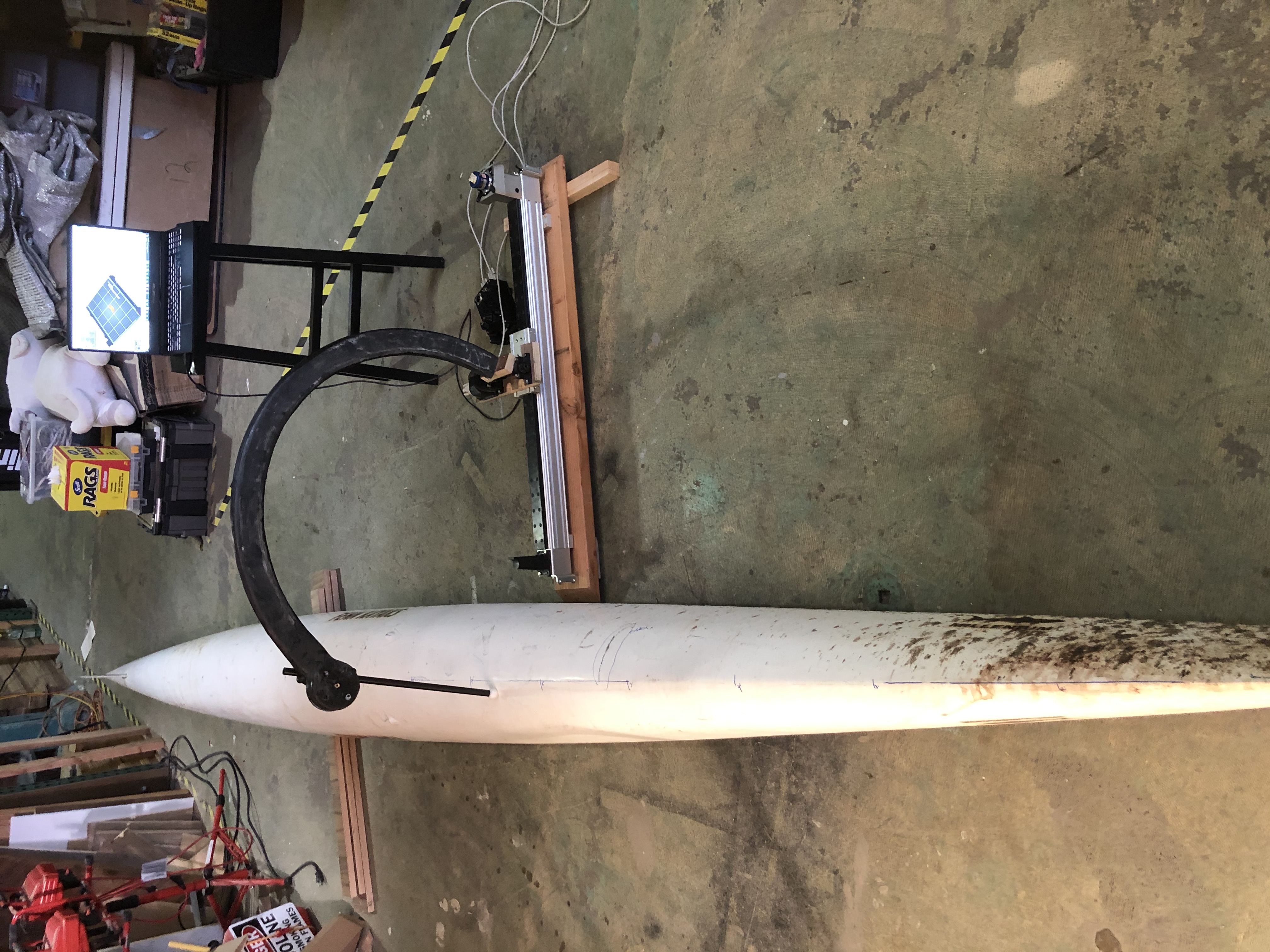
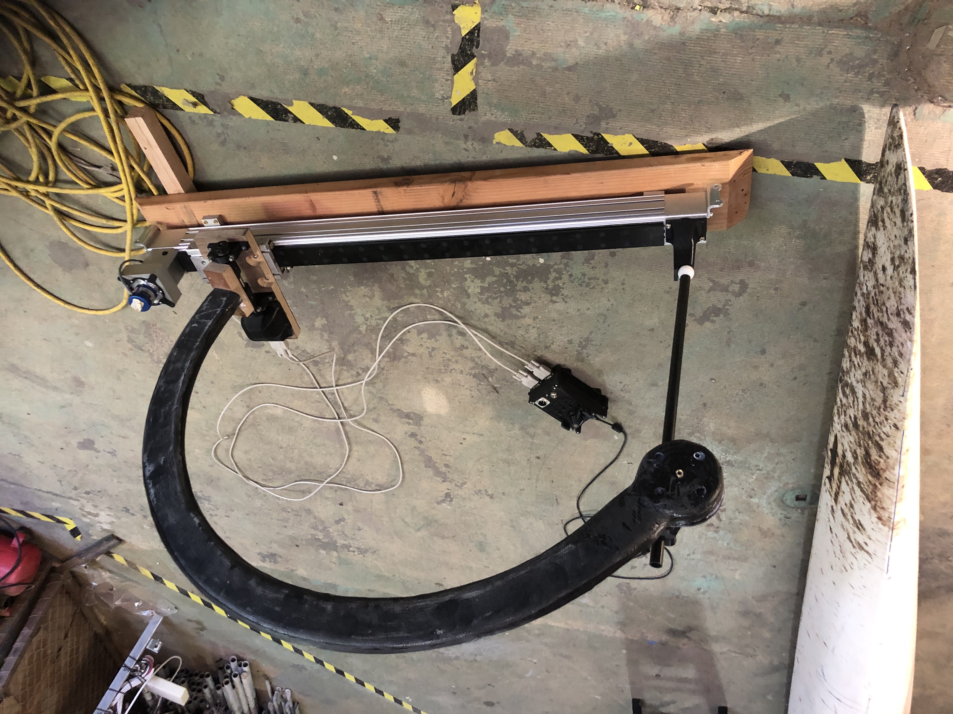
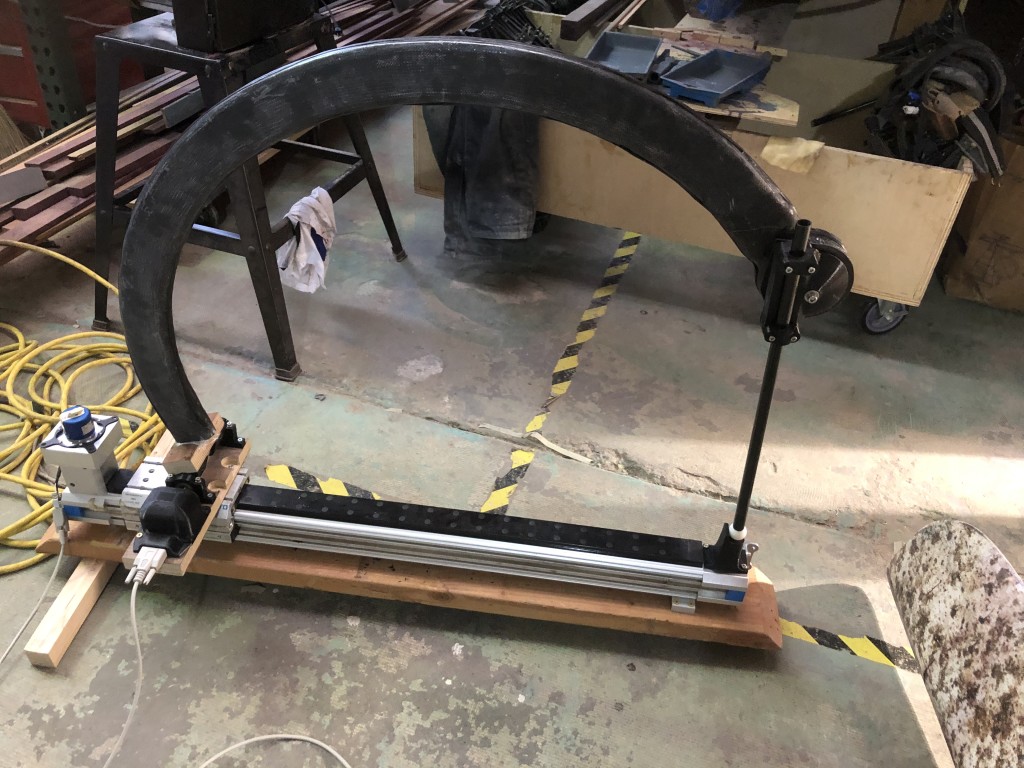
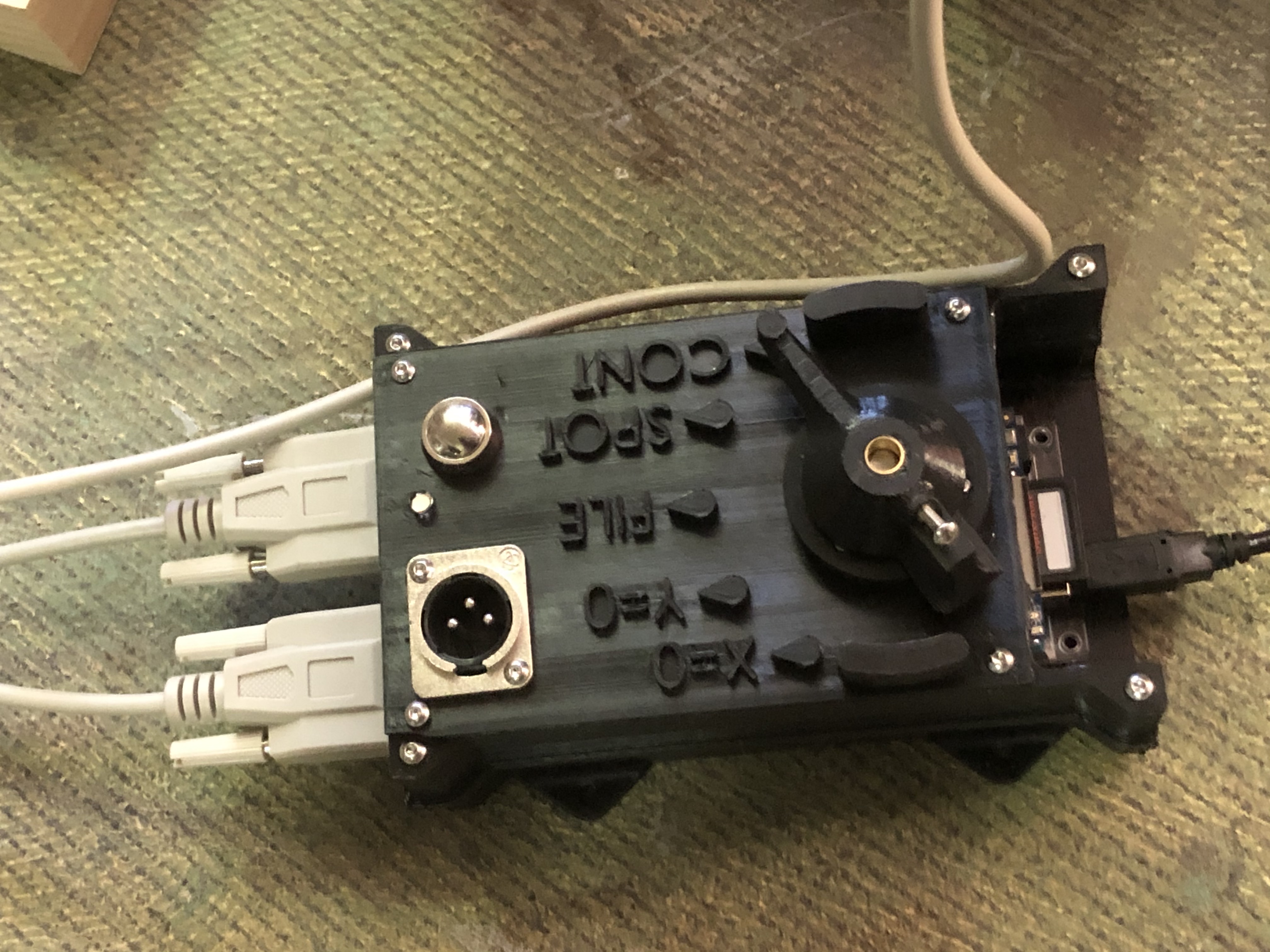
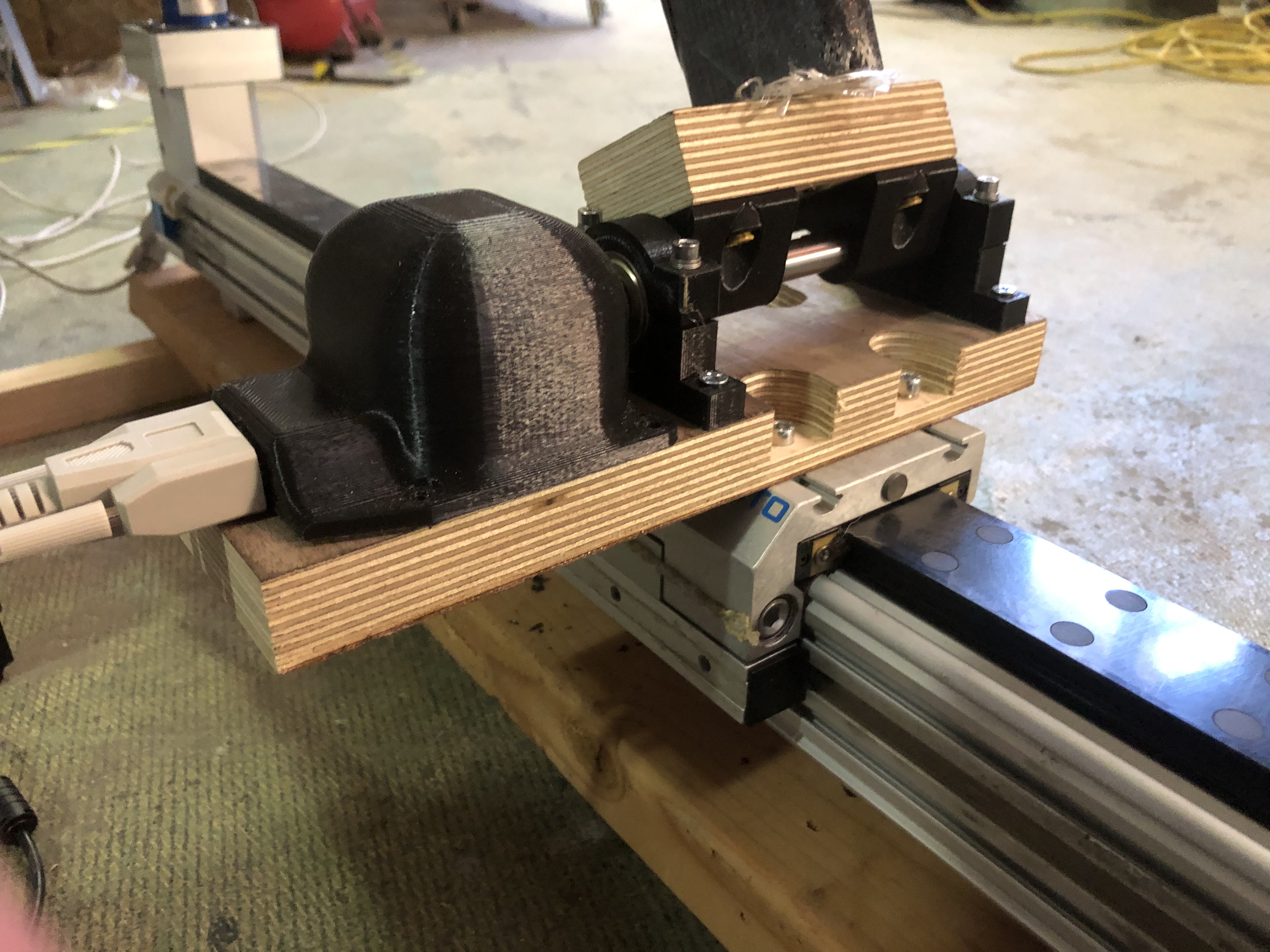
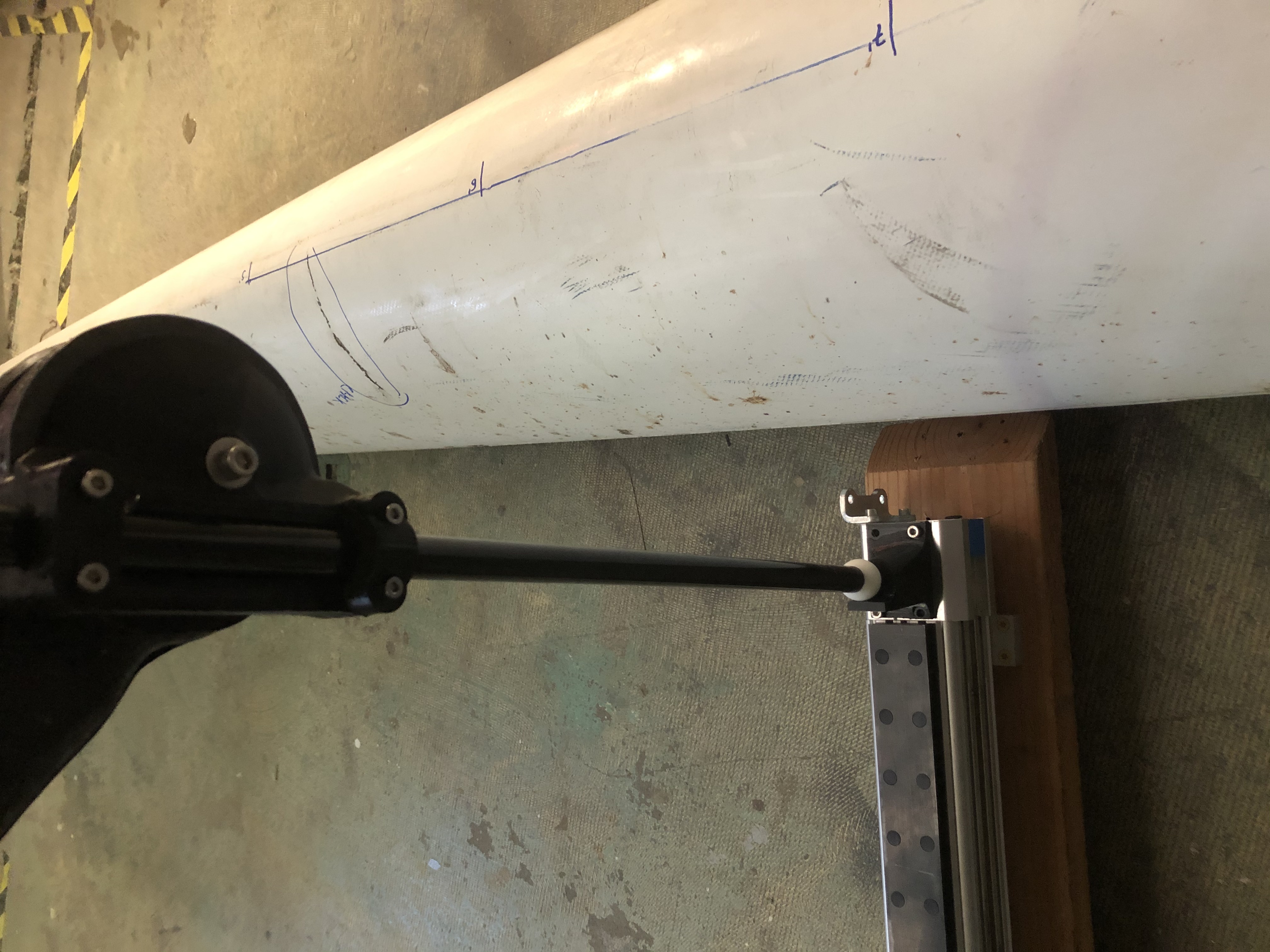
Anyway… today (4/2/21) I got it all working and now I have a gizmo that can scan curvy boat hulls very accurately, allowing me to make parts that fit and extend the hull very smoothly. Hooray! Hull Scans will be updated tomorrow:-)
Source Code for the Data Logger Touch Probe:
/* Two-Encoder Data Logger for Measuring Hull Shape
* Gordon Kirkwood March-April 2021
* based on two-encoder reader example code, and SD library data logger source code
42 black LED+
40 white LED-
38 gray button sw
36 purple button sw
34 blue COMMON return of selector switch- ground it
32 green continuous record mode- (?while button pressed, or until pressed again? At ~10hz or every 5mm pathlength from last point?)
30 yellow spot record mode – record a datapoint upon each button press (rising edge)
28 orange “file” mode- button press initiates a new file. Press between each segment.
26 red “Y=0” calibration zero – button press sets Y value to zero (do this while ball on stand)
24 brown “X=0” calibration zero – button press sets X value to zero (do this while ball on stand)
18,19- X channel encoder's quadrature inputs
20,21- Y channel encoder's quadrature inputs
*/
//included libraries
//NOTE: The most recent SD card library does NOT work with my older SD shield on the mega, I had to hunt around, find the older library,
//uninstall (move out of the libraries folder) the default (current) SD library, and install the older version before it would recognize my SD shield
//link to the older SD shield library and explanation: https://learn.adafruit.com/adafruit-data-logger-shield/for-the-mega-and-leonardo
#include <Encoder.h>
#include <SPI.h>
#include <SD.h>
//values used for the return of modes from the identify_mode() function
#define MODE_CAL_X 1
#define MODE_CAL_Y 2
#define MODE_FILE 3
#define MODE_SPOT 4
#define MODE_CONT 5
#define MODE_UNKNOWN 0
//define the two input encoders on the scanner
Encoder knobX(18, 19); //on the arduino mega, pins 2,3,18,19,20,21 are able to external-interrupt, giving fastest response to encoders.
Encoder knobY(20, 21);
const int chipSelect = 10; //setup for SD shield
unsigned long time; //for tracking how frequently to output coordinates, when time-limiting the output rate
unsigned long nexttime; //this value is set when a value is output, as the soonest the next output should occur\
//these values store millisecond counts
unsigned long save_every_X_ms = 1000; //time interval at which position is logged to datafile, if limited free-running sampling mode (not used)
//in milliseconds, presuming one or more values has changed since the last logged coordinates.
//if values haven't changed since last last logged coordinates, no new value is recorded.
//FOR FUTURE MOD: compute the approximate distance traveled since last data coordinates,
//and attempt to log datapoints at semiuniform intervals of spatial coordinates, possibly with
//allowance for corners and where there are sharp changes in coordinates, where values might be recorded
//at finer spatial increments.
//otherwise I will perform this resampling in matlab or similar postprocessing software.
File dataFile; //sd card data structure
char filename[16]; //string to read in and manipulate filenames in
/* pins for mode selector (grayhill multipole switch) user input knob, and the wire colors connected to them, are included in the following pinout table
* MEGA PIN wire color function
42 black LED+
40 white LED-
38 gray button switch
36 purple button switch (short the two leads to trigger spot recording, or select various options.
34 blue COMMON return of selector switch- ground it
32 green continuous record mode- (?while button pressed, or until pressed again? At ~10hz or every 5mm pathlength from last point?)
30 yellow spot record mode – record a datapoint upon each button press (rising edge)
28 orange “file” mode- button press initiates a new file. Press between each segment.
26 red “Y=0” calibration zero – button press sets Y value to zero (do this while ball on stand)
24 brown “X=0” calibration zero – button press sets X value to zero (do this while ball on stand)
*/
int LED_HIGH_PIN =42;
int LED_LOW_PIN =40;
int BUTTON_PULL_PIN =38; //write low on this
int BUTTON_READ_PIN =36; //input_pullup on this - when connected by bytton to BUTTON_PULL_PIN it will be pulled down
int MODE_RETURN_PIN = 34; //set to low, then set input mode pins to input pullup, mode pins are active when grounded
int MODE_CAL_X_PIN = 24; //grounded to MODE_RETURN_PIN if CAL_X mode selected
int MODE_CAL_Y_PIN = 26; //grounded to MODE_CAL_X_PIN if CAL_Y mode selected
int MODE_FILE_PIN = 28; //etc...
int MODE_SPOT_PIN = 30;
int MODE_CONT_PIN = 32;
long inter_blink_interval = 200;
long blink_duration = 50;
//main loop variables
long newX, newY; //to tell if values are changed, I compare new values and old values at each update.
long x = 0; //initialize local variables for both enncoders, here called x and y (channel). note that the encoder datastructure maintains a separate internal private variable for position, so
//to calibrate or zero values requires encoder.write(val); to be called, not just setting these values to zero.
long y = 0;
long min_delta_Y = 10; //minimum increment of Y encoder between recorded datapoints - the larger this value, the less frequently datapoints will be written
long min_delta_X = 10; //minimum increment of X encoder between recorded datapoints.
int mode = 0; //use mode definitions in header for various operating modes
int last_mode = 0; //track if mode has changed
int button = 1; //button status. input pullup defaults to 1 in case of no buttonpress.
int last_button = 1; //track if button changed from last evaluation. initialize to 1 because default (without button press) is input_pullup, so defaults high.
//************************************************************************************
void beep_LED(){ //turns on LED for 100ms.
digitalWrite(LED_HIGH_PIN,HIGH);
digitalWrite(LED_LOW_PIN,LOW);
delay(100);
digitalWrite(LED_HIGH_PIN,LOW);
}
//************************************************************************************
void increment_filename()
//this function searches for files with a name matching a certain pattern, incrementing a counter variable present in the filename until it encounters a name which doesn't exist\\
//note: if files are removed from the directory, so that there is not a full sequence of files prefix000, prefix001, etc... up to prefixNNN, this code will fill those gaps, resulting in nonlinear sequence of files.
{
long lastblink=0,nextblink = 0;
lastblink = millis();
nextblink = lastblink + inter_blink_interval;
if (dataFile) {//close file if it is open, because we'll be creating a new file.
Serial.println("closing previously open datafile.");
dataFile.close();
Serial.print("echoing contents of previous file:");
Serial.println(filename);
Serial.println("****************************************** begin echoing file>>");
dataFile = SD.open(filename);
while (dataFile.available()) {
Serial.write(dataFile.read());
if (millis() > nextblink) //blink LED while data file being echoed over serial port, so that you know that device is not yet ready to record new data.
{
beep_LED();
nextblink = millis() + inter_blink_interval;
}
}
Serial.println();
Serial.println("****************************************** Done echoing file.");
}//if datafile exists
else
{
Serial.println("datafile was not open");
}
//below code finds initial file name to begin with (may be repeated in main loop if button pressed while in "file" mode, to increment filename.
int n = 0; //terating variable for file numbers in names with a consistent pattern
// initialize filename in the consistent pattern chosen
snprintf(filename, sizeof(filename), "data%03d.txt", n); // includes a three-digit sequence number in the file name
//search for filenames in given pattern until the name DOESNT exist- thats the next file.
while (SD.exists(filename)) {
n++;
snprintf(filename, sizeof(filename), "crv%03d.txt", n);
}
//now filename[] contains the name of a file that doesn't exist
//to open file for writing eg in main loop:
Serial.print("opening file: ");
Serial.println(filename);
dataFile = SD.open(filename, FILE_WRITE); //THERE WAS MY PROBLEM: I HAD variable type before dataFile (ie. File dataFile), which compiler understood to define a LOCAL variable, overriding / taking precedence over global dataFile variable.
if (dataFile) { //if file was opened OK
// Serial.println(n);//number of file
Serial.println("Successfully opened file.");
//do not close file; it must remain open to accept data written.
dataFile.println(filename); //for testing purposes write the file's name into the file itself as a header.
//dataFile.close();
}
else {//error opening file
Serial.println("error opening file");
while (1); // end execution.
}
}
//************************************************************************************
void setup() {
Serial.begin(9600);
Serial.println("FormScanner 3/29/2021 Gordon C Kirkwood");
//now setup the data card
Serial.print("Initializing SD card...");
pinMode(SS, OUTPUT);
//setup LED as output
pinMode(LED_HIGH_PIN,OUTPUT); //LED high pin
pinMode(LED_LOW_PIN,OUTPUT); //LED low pin
//blink LED once to indicate circuit coming alive.
digitalWrite(LED_HIGH_PIN,HIGH); //this pin will toggle to turn LED on and off
digitalWrite(LED_LOW_PIN,LOW); //this pin will remain low
delay(100);
digitalWrite(LED_HIGH_PIN,LOW);
//button press detection
pinMode(BUTTON_PULL_PIN,OUTPUT); //button pulldown
digitalWrite(BUTTON_PULL_PIN,LOW); //leave this pin low; it will short out the weakly-pulled-high button_read_pin input.
pinMode(BUTTON_READ_PIN,INPUT_PULLUP); //button read, active low (button press causes button_read_pin to go low.
//setup mode selector knob
pinMode(MODE_RETURN_PIN, OUTPUT);
digitalWrite(MODE_RETURN_PIN, LOW); //pull low
pinMode(MODE_CAL_X_PIN,INPUT_PULLUP); //grounded to MODE_RETURN_PIN if CAL_X mode selected
pinMode(MODE_CAL_Y_PIN,INPUT_PULLUP); //grounded to MODE_CAL_X_PIN if CAL_Y mode selected
pinMode(MODE_FILE_PIN,INPUT_PULLUP); //etc...
pinMode(MODE_SPOT_PIN,INPUT_PULLUP);
pinMode(MODE_CONT_PIN,INPUT_PULLUP);
// see if the card is present and can be initialized:
if (!SD.begin(10, 11, 12, 13)) { //these are the pins for connection to older adafruid arduino SD shield; not same for current generation of boards.
Serial.println("Card failed, or not present, halting.");
// don't do anything more:
while (1) ;
}
Serial.println("card initialized.");
//timer initialization for write-every-so-on timing
time = millis();
nexttime = time;
increment_filename(); //find a filename that is new, and open it.
knobX.write(0);
knobY.write(0); //ensure both encoders start with a default zero value.
} //setup ends with a data file opened, a file structure variable named "dataFile", and a character array "filename[]" containint it's name.
//in the subsequent loop, it may be necessary to find a "next file name", by closing the existing file.
// \code to open and test file. ****
//************************************************************************************
void echo_mode(int m) //for debugging over serial port, echo what the mode select switch is
{
switch (m) {
case MODE_CAL_X:
Serial.println("CAL_X");
break;
case MODE_CAL_Y:
Serial.println("CAL_Y");
break;
case MODE_FILE:
Serial.println("FILE");
break;
case MODE_SPOT:
Serial.println("SPOT");
break;
case MODE_CONT:
Serial.println("CONT");
break;
default:
Serial.println("mode unknown");
break;
}//switch
}
//************************************************************************************
int read_mode() {
//function identify_mode() reads the mode pins by setting the common pin low, and all the poles of the selector go to input_pullup pins. Returns an integer MODE code, as defined in header, signifying which mode.
/* pins for mode selector knob are included in the following pinout table
* MEGA PIN wire color function
42 black LED+
40 white LED-
38 gray button sw
36 purple button sw
34 blue COMMON return of selector switch- ground it
32 green continuous record mode- (?while button pressed, or until pressed again? At ~10hz or every 5mm pathlength from last point?)
30 yellow spot record mode – record a datapoint upon each button press (rising edge)
28 orange “file” mode- button press initiates a new file. Press between each segment.
26 red “Y=0” calibration zero – button press sets Y value to zero (do this while ball on stand)
24 brown “X=0” calibration zero – button press sets X value to zero (do this while ball on stand)
*/
digitalWrite(MODE_RETURN_PIN,LOW); //make sure the mode_return_pin is able to pull any selector contact low
if (0==digitalRead(MODE_CAL_X_PIN)){return MODE_CAL_X;}
if (0==digitalRead(MODE_CAL_Y_PIN)){return MODE_CAL_Y;}
if (0==digitalRead(MODE_FILE_PIN)){return MODE_FILE;}
if (0==digitalRead(MODE_CONT_PIN)){return MODE_CONT;}
if (0==digitalRead(MODE_SPOT_PIN)){return MODE_SPOT;}
return MODE_UNKNOWN;
}
//************************************************************************************
int read_button(){
//I need to modify so I only detect rising edges, and debounce button. for now, debouncing in the calling-code, with a short delay.
digitalWrite(BUTTON_PULL_PIN, 0);
return(digitalRead(BUTTON_READ_PIN));
}
//************************************************************************************
void save_values(long thisx, long thisy, long thisz){
//writes an XYZ triplet to the already open datafile.
//assumes that datafile is already open for writing to.
// make a string for assembling the data to log:
String dataString = "";
// read encoder values and put into a string to write to file
dataString += String(newX);
dataString += " ";
dataString += String(newY);
dataString += " ";
dataString += String(0); //solidworks wants triplets, ie XYZ values, so write a constant 0 at the end of each row. (Z placeholder)
dataFile.println(dataString); //************
//dataFile.flush(); //************
Serial.println(dataString);
}
//************************************************************************************
void loop() {
newX = knobX.read();
newY = knobY.read();
//x and y record the last values of these, and are only updated to the newX and newY values upon a data-save event, so that I don't record duplicate values in the file.
mode = read_mode();
while (mode == MODE_UNKNOWN) mode = read_mode(); //wait until the value settles when switching between settings;
//because the switch breaks contact first, then makes next contact ("break before make") so transitions are noisy
//update mode display only when the mode changes
if (last_mode != mode){
echo_mode(mode);
last_mode = mode;
}
//echo if rising edge on button press
button = read_button();
if (button && !last_button) //rising edge
{
Serial.println("button pressed!");
delay(100); //crude debounce, but effective since data collection rate is slow.
//insert code here to handle various modes.
switch (mode) {
case MODE_CAL_X:
Serial.println("button detected in CAL_X mode, setting X-> 0");
knobX.write(0);
break;
case MODE_CAL_Y:
Serial.println("button detected in CAL_Y mode, setting X-> 0");
knobY.write(0);
break;
case MODE_FILE:
Serial.println("button detected in FILE mode, starting a new file.");
increment_filename();
break;
case MODE_SPOT:
//write a line of text to the file
//newX and newY were already read at the start of the loop, no need to re-read them.
//check if (position has changed on either encoder since x and y were last written to the file (and newx value propaged to stored X, and newY propaged to stored Y)
if ((x != newX) || (y != newY)) //only save values if different from before.
{
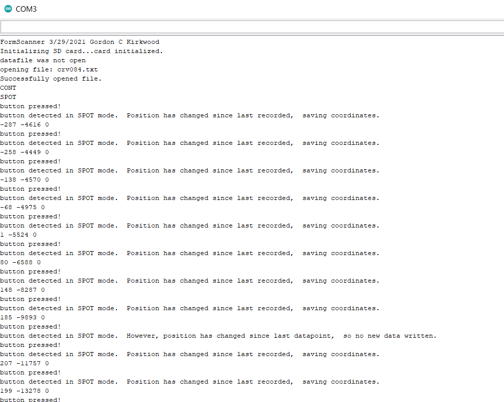
Serial.println("button detected in SPOT mode. Position has changed since last recorded, saving coordinates.");
x = newX; //update position trackers so the "value changed" test above can detect subsequent changes.
y = newY;
save_values(x,y,0);
}
else
{
Serial.println("button detected in SPOT mode. However, position has changed since last datapoint, so no new data written.");
}
break;
case MODE_CONT:
Serial.println("button detected in CONTINUOUS mode. However, button has no effect in continuous mode. Data is recording by default");
break;
}//switch
}//if button pressed
last_button = button;
if (mode==MODE_CONT)
//continuous data logging means no button press required to trigger it.
//plan: check if X or Y encoder has changed by at least min_X_increment or min_Y_increment. if either encoder has changed by at least this much, then record the datapoint to the file.
//also record to file regardless of change in X or Y since last recorded, if the mode has JUST changed to MODE_CONT.
if (((abs(x-newX) >= min_delta_X) || (abs(y-newY) >= min_delta_Y)) || (last_mode!= MODE_CONT)){
x = newX;
y = newY;
save_values(x,y,0);
Serial.println("CONT mode, motion detected, datapoint written.");
}
}//loop
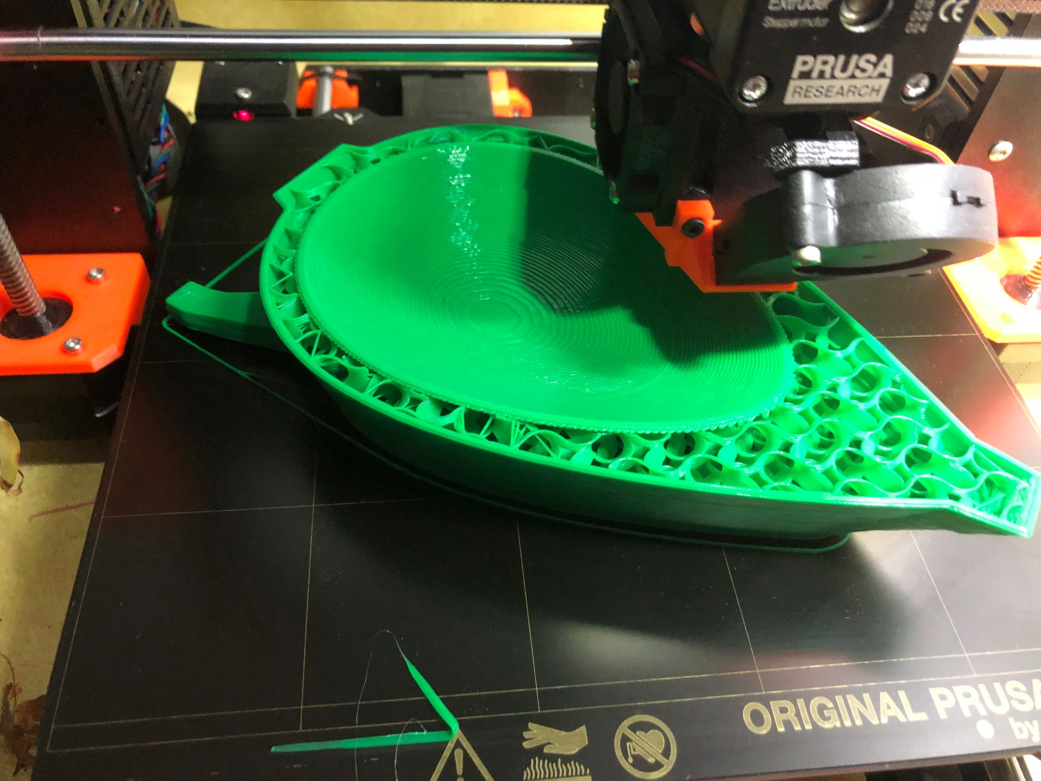
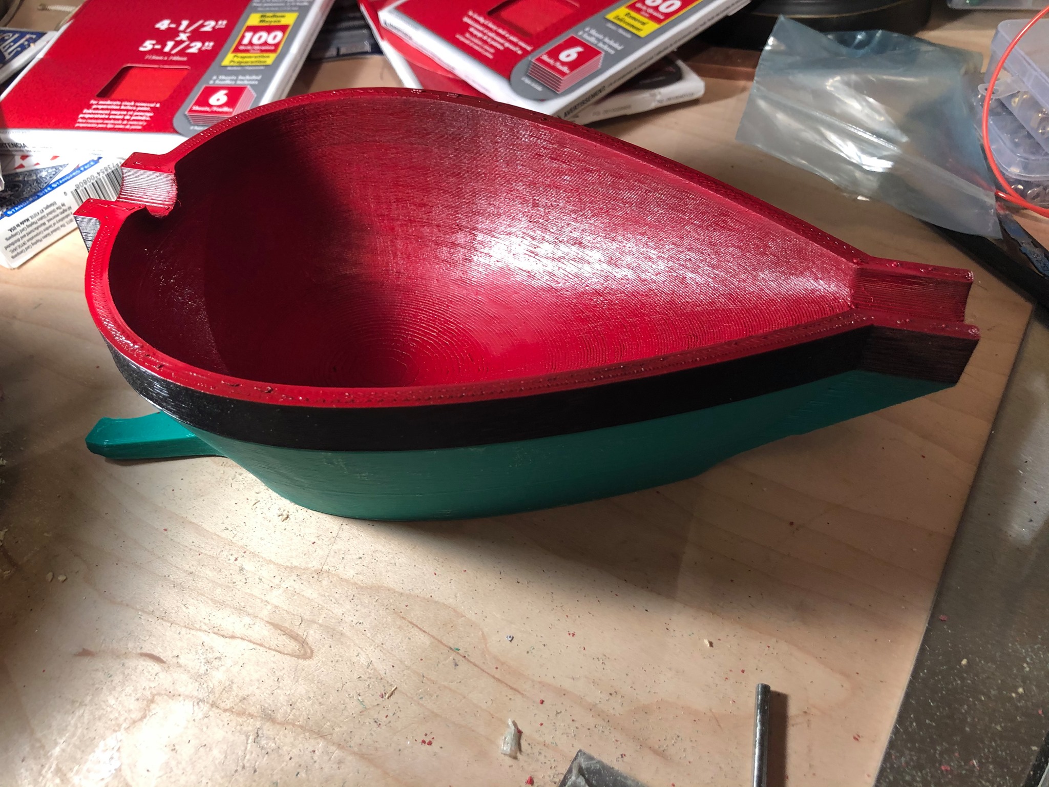
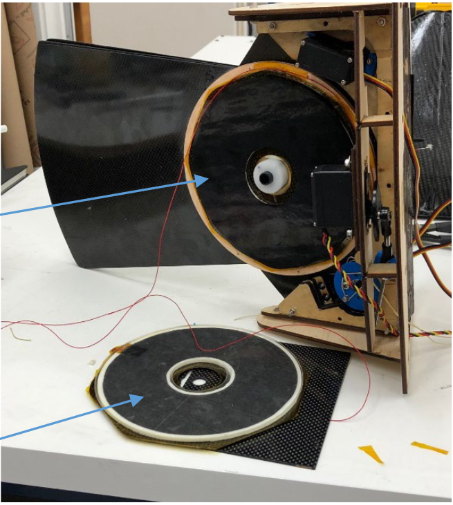
Rapid prototyping of Composite Aerospace Parts with 3d printed molds
I needed a lightweight, impact resistant, streamlined fairing for a flying robot. I could 3d print a part with the right shape, but 3d printed materials would either be too weak, or too heavy. I’ve been considering a hybrid workflow which this was the perfect opportunity to try out: 3d printing a mold for composite layup.
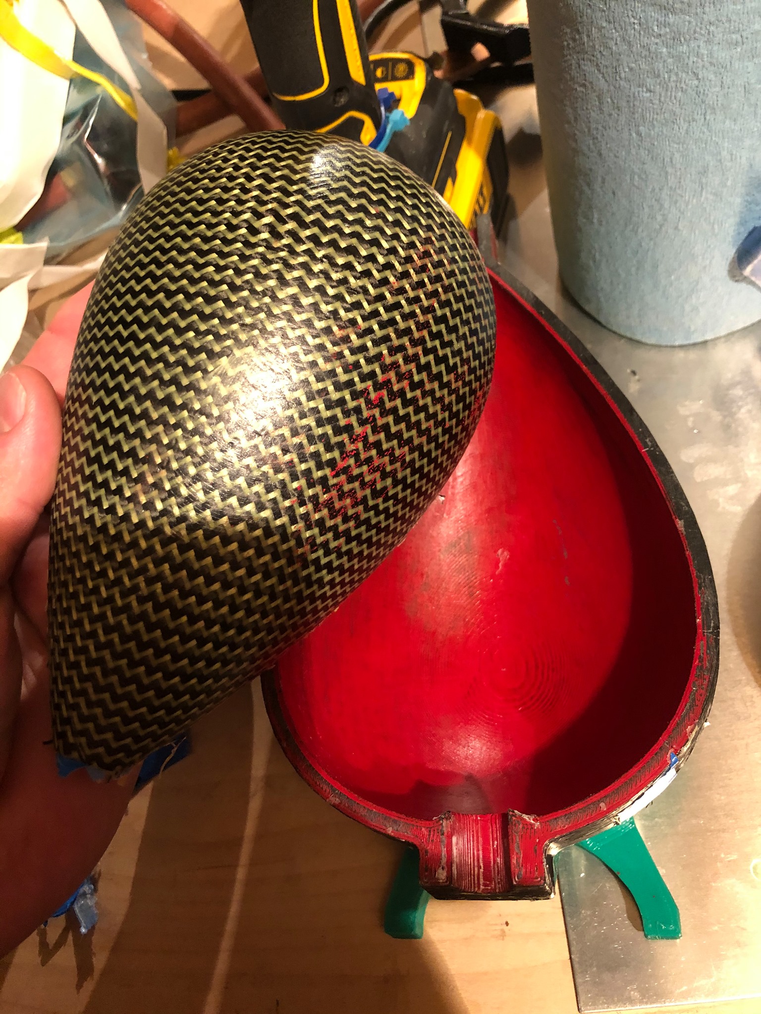
It worked wonderfully! The mold printed overnight, and after some sanding primer was applied and sanded down to a 600 grit finish, I waxed the mold, and it was ready to invest with fabric. I vacuum bagged the parts for good consolidation, and am very pleased with the results, shown above.
US Patent #10,710,247 Issued to Kirkwood et al for new Robotic “Conical Iris Gripper”
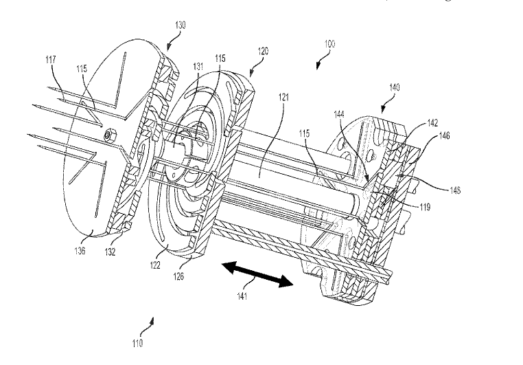
I was issued US Patent number 10,710,247 on July 14th 2020 for a new type of robotic gripper device uniquely able to grasp difficult-to-grasp food items.
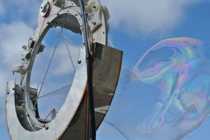
Robotic preparation of food is hard, in part, because of the difficulty of grasping and manipulating irregular shaped, slippery, and loose aggregated cooking ingredients like chopped onions, shrimp, or loose lettuce. I was asked to consider if any new design could meet the needs of this task, and prototype it. From my previous work with mechanical iris development inspired by the international space station’s Canadarm gripper, (see: CNC Bubble Iris), I realized that a novel 3-degree-of-freedom gripper could meet this need: a conical cage of slender spears, which could change shape in three different ways: taper angle, diameter, and extension. With these motions, I realized it was possible to make a highly effective gripper with a wide repertoire of potential grasping strategies, which could allow for a huge range of ingredients to be handled by a single gripper. The gripper can either open or close like a hand gathering and grabbing a handful of food, or stab like a fork, push food off of that fork, or dispense loose food items gradually, e.g. ‘sprinkling’. This gripper went on to become the primary end effector for a $1M+ commercial research project
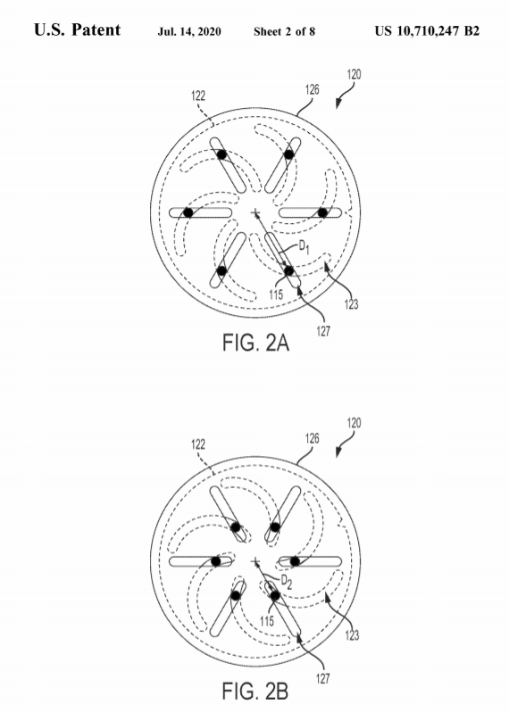
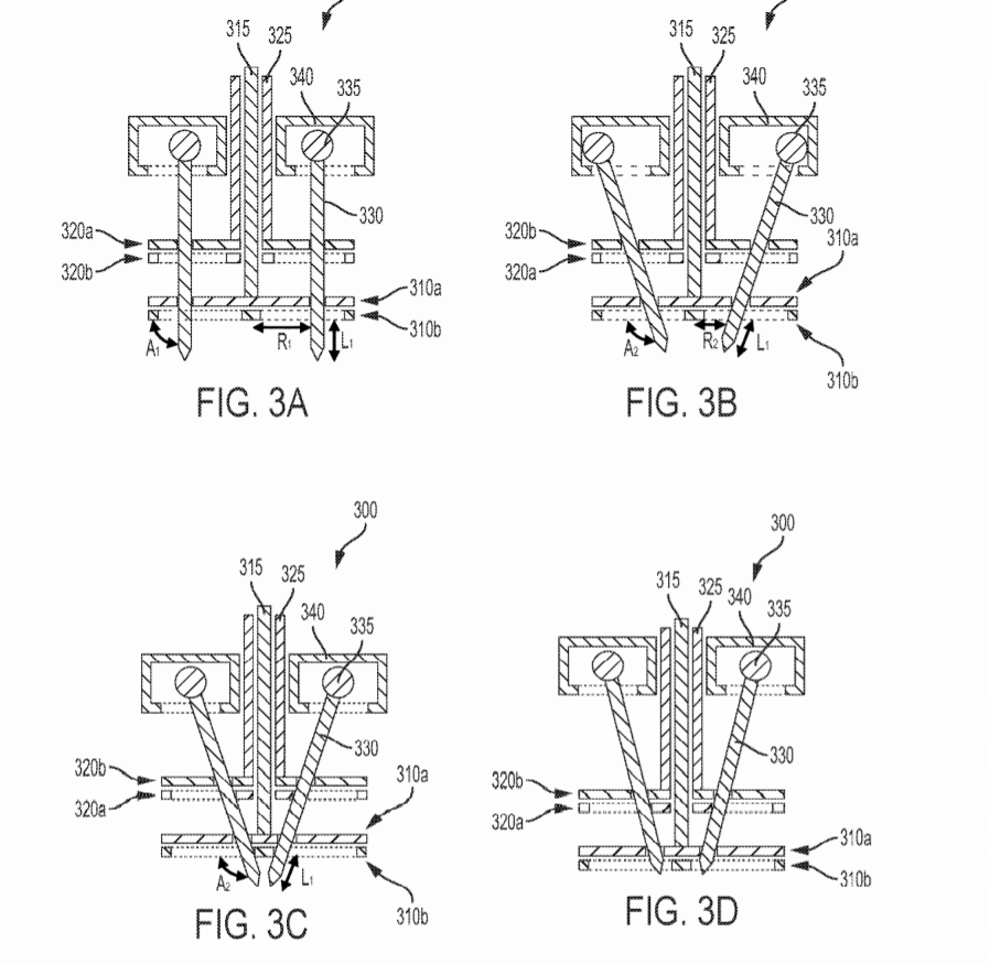
The conical iris gripper was rapid prototyped with 3d printing, laser cutting, OEM parts, and a minimum of machining, over the span of about two weeks with other projects going on. The initial prototype was made using mostly laser cut acrylic and off the shelf parts, with a materials cost of less than $150.
“Enabling Biomimetic Morphing UAVS” paper published in Twenty-Second International Conference on Composite Materials (ICCM22)
I’m pleased to release a new publication in the Twenty-Second International Conference on Composite Materials (ICCM22) entitled “Enabling Biomimetic Morphing UAVs” with colleagues at SRI, the University of Southern California, and NextGen Aeronautics.
This publication details one application of a technology I have helped develop with my colleague Roy Kornbluh at SRI: ultra-lightweight, ultra-low power, electrolaminate clutches and mechanical multiplexers for reconfigurable systems in aerospace, astronautical, and terrestrial robotic applications.
My role in this project was to mechanically design a demonstrator tailfin assembly using these new lightweight, low power, electrolaminate clutches to lock control surfaces of aerial vehicles into variable area configurations. I did all the mechanical and electrical design as well as composite fabrication of the carbon fiber tail and rear fuselage assembly.
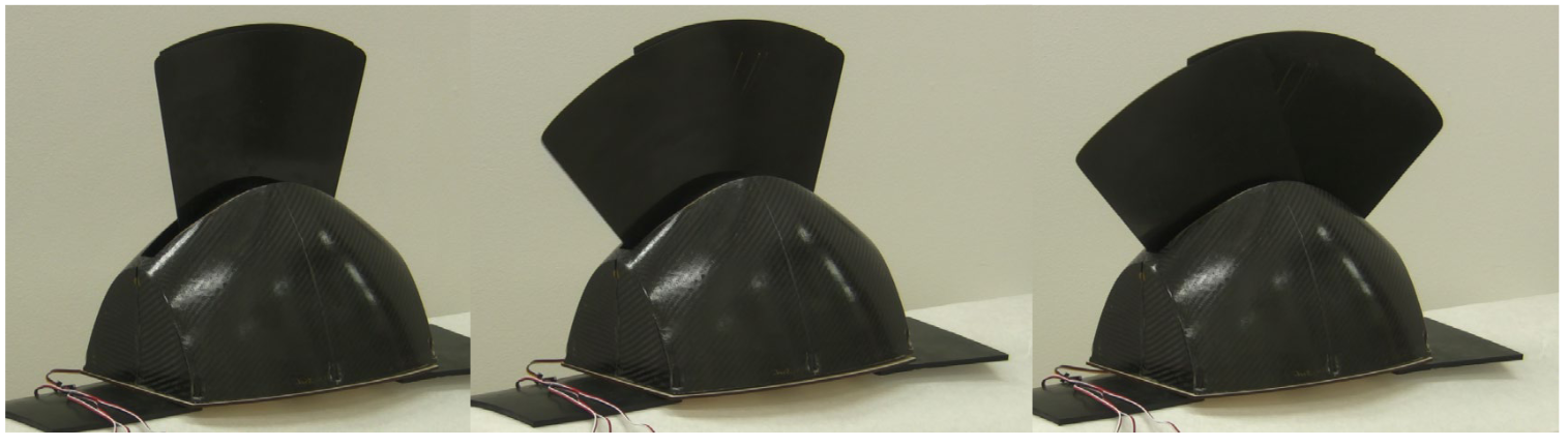
Abstract: This paper reports on the design and testing of a practical, morphing wing aircraft. We intentionally mix and match elements of avian inspired design with novel technologies and proven mechanical components to provide a demonstrator aircraft that shows, in the simplest way, what benefits accrue from basic morphing changes. The simplest and most beneficial morphing concept is to change the wing area and aspect ratio, and it is easy to show that, for an otherwise fixed example configuration, a factor of three decrease in wing planform area can sustain a predicted lift:drag ratio, L/D = 9, when the vehicle flight speed U doubles from 12 to 24 m/s. Without morphing, L/D would be 6.5. Such a large area change can be achieved with a telescoping wing, which is not biomimetic, but is practicable and achievable using standard and custom 3D printed components. We combine this variation with a tail-body configuration that is bio-inspired, and suggested by previous and continuing work on the vehicle-level flight efficiency of tailless aircraft, where a standard tail geometry is replaced by a trailing edge flap that converts the cargo-carrying body into a lifting body. The practical shape-changing is enabled by the use of novel electrolaminate materials that can quickly change stiffness at varying positions/postures.
Protected: Make your own giant Kirkwood Bubble Iris!
A small concert for solo cello, deep inside the Grand Canyon, during a meteor shower.
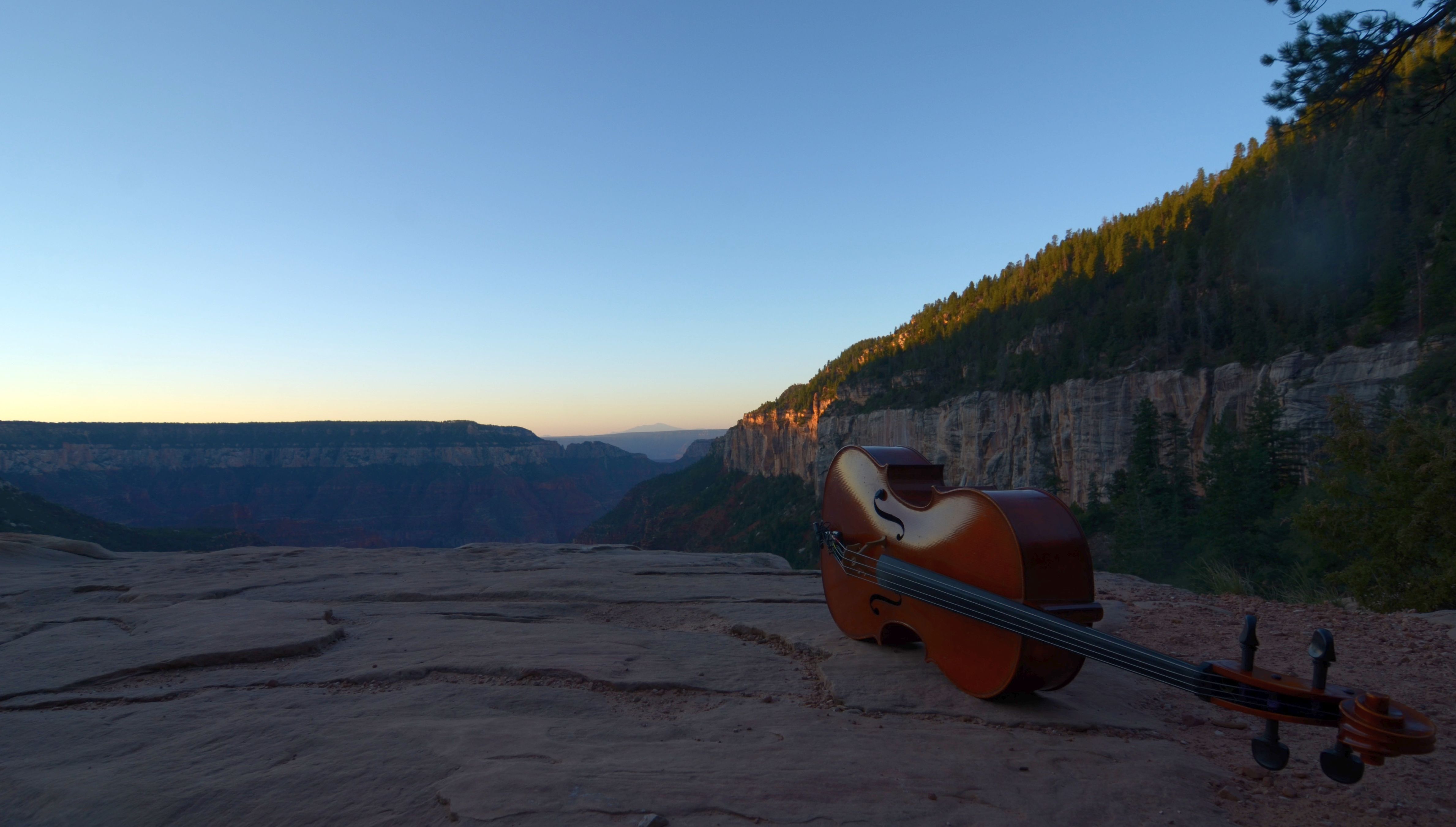
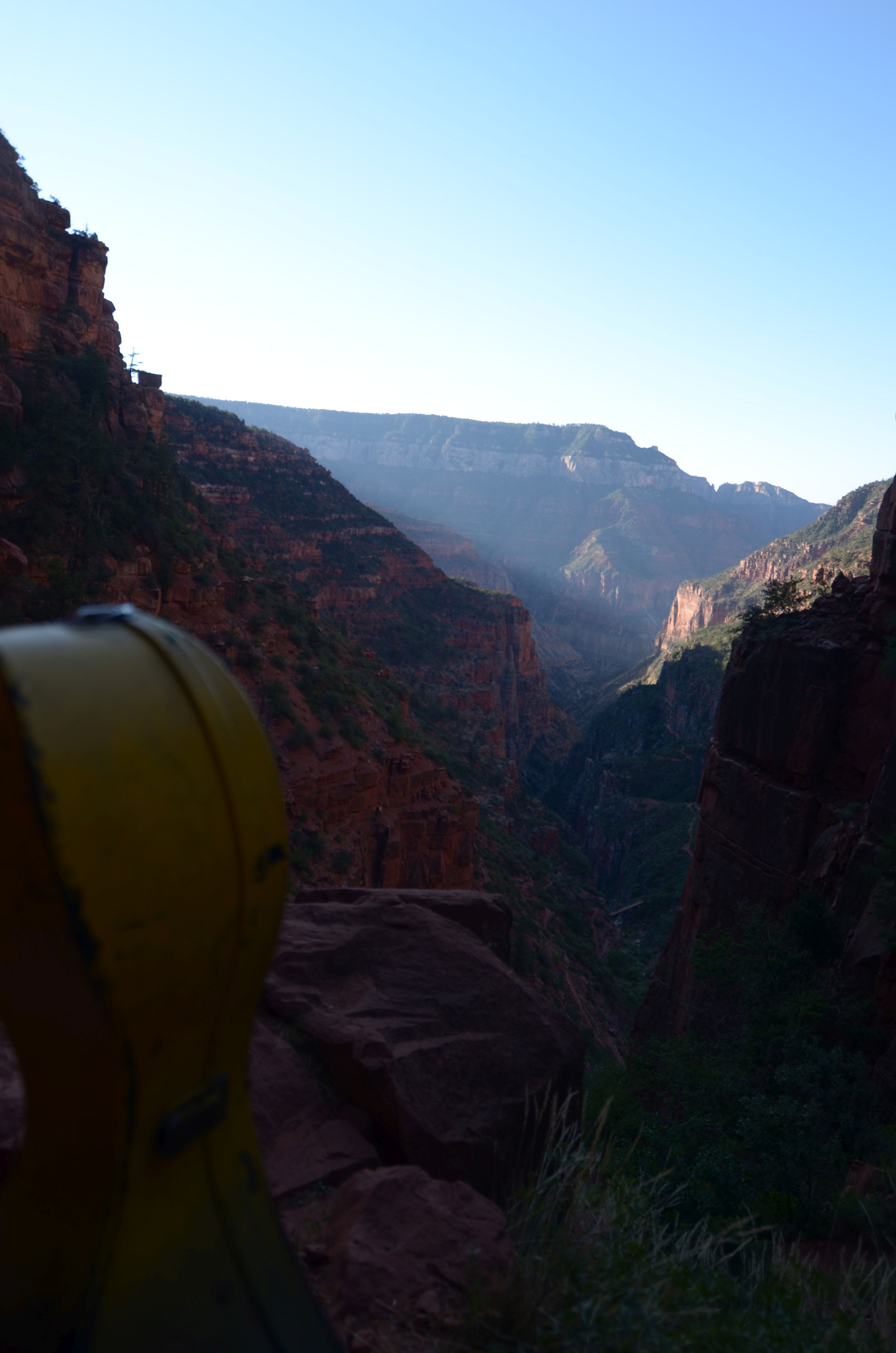
Six years ago, while hiking rim-to-rim in the Grand Canyon the first time, I discovered a profoundly spectacular location with interesting acoustics. A wooden footbridge crossed a chasm, forming a convenient stage, with sheer rock walls ascending close together towards the north rim of the canyon, 2000′ overhead. The Kaibab trail is even, in spots, blasted as a “C” shaped ledge into a sheer-vertical cliff face. It is the largest and most topographically interesting space I’ve ever gotten to sing in.
What stood out, to my ears, was the unusual quiet and echo. It is free of almost any noise, except the sounds of small ground squirrels or birds traipsing in the underbrush. But when a sound was made, the echoes were unusually distinct and lively. Echoes would echo, and echo, and it seemed you could hear the fourth or fifth reflection of a handclap. I stopped and whistled for a few minutes, and remember thinking to myself, wistfully:
“If only I had my cello”.
Six years passed. A time of incredible growth and flux, and now I find myself living on the west coast, theoretically within a day’s drive of this spot. (13 hours from the San Francisco bay). The idea is still high among my crowded backlog of adventures / projects / enthusiasms. And then the news arrives, that the Perseid meteor shower this year (a regular August occurrence) was expected to be unusually brilliant this year, “The brightest in a decade” even. This finally pushed the idea (of revisiting the North Kaibab trail with my Cello) from “A good idea worth doing sometime” to “A unique opportunity to do now“. I messaged a few friends to inquire if anyone wanted to go, and join me in a middle-of-the-night cello recital on a footbridge in the canyon, beneath the brightest meteor shower of a decade. Many were interested but could not attend due to prior commitments, or the extreme driving:hiking ratio (near 2:1). but the invite met an enthusastic “yes” from a friend who, it turns out, was more apt a fellow adventurer than I could have known beforehand: not only a willing impromptu adventurer, but an aerialist/gymnast/theatrical producer, with extraordinary insights and ideas about unconventional audience/performer relationships.
Talking to Strangers: Lou Fischer

I was bicycling by starlight in the middle of the desert at midnight, 20 miles from anywhere in the middle of Goblin Valley Utah, in late August. Crossing deserts during the night is necessary when the daytime shade temperature is between 110 and 120F (but there is no shade) and ground temperatures reach 150F before noon. But it is also a treasure to ride in the desert at night: the skies are the clearest of anywhere on the continent. One day before the August full moon, I was riding by star and moon light alone. Nobody was on the road. Cars would pass maybe once every half hour or two, and when they did, I could see their headlights ten minutes away, hear their roar minutes away. I’d been riding this way, solo, for a few hours, racing towards Moab Utah and Arches NP trying to arrive on my birthday and see the full moon rise over these incredible landscapes, when I saw a parked car on the side of the road up ahead, lights off, with it’s trunk open, and a fellow standing next to it.
I should mention that, when asking locals about what to expect, before crossing the 100 miles of open Mojave desert a few weeks back, from Joshua Tree to the Colorado river, multiple independent sources repeated several times “It’s where people go to bury bodies”, or “Ever seen ‘the Hills have Eyes’?”.
But I saw his camera tripod, and no bodies. I had also benefited previously from a trucker who stopped and shared an ice chest of gatorade with me in the middle of the Mojave desert; here was an opportunity to pay it forward. And I was curious.
He certainly did not expect a jovial Gordon “hello, howdy! Are you okay, need any water?”. Not when the loudest thing he’d likely experienced for his last hour was the click of his camera shutter, sand underfoot, and what night creature sounds as occur in August, in the deep sand and sagebrush desert, at midnight. I tried to mitigate his shock by speaking from a respectful safe distance of 50 feet or so.
To say he was “Startled” would be an understatement. We were in one of the most desolate places in the country, after midnight, in the dark. He’d probably felt himself the only person for miles, ten seconds prior. Bicycles riding by starlight are stealthy! I saw him reassure himself (discretely) of the location of a bottle of bear-spray on his hip, his countermeasures. I had sympathy for this; I had done similar before hailing him. We were both assessing each other. And then we talked.
We progressed quickly from threat-assessment to rapport and shared enthusiasm. Two gearhead adventurers, alone in the middle of the desert at midnight talking under starlight . We talked for over an hour. Before I resumed bicycling, he made me promise to message him before I arrived in Chicago, where he would host me. He also took this picture of me, which is one of my favorites of the whole trip:

Lou is a photography buff and documentary filmmaker, his youtube channel is “Bonneville Stories”. Some of his work is linked below. His brother held a land – speed record on motorcycles; He was in town to document the fastest motorcycle in the world, the BuB streamliner motorcycle, which reaches in excess of 360MPH / Mach 0.5. I often think of this encounter as one of the more rewarding “talk to strangers” lessons in good faith optimism… especially since pessimism could easily have prejudiced this introduction to nonexistence. It would have been easy to make an excuse to pass a car in a desolate area.
This story, from six years ago, came to mind in the context of two especially significant meetings this last week and next, discussing character development and education in science, technology, engineering and math with DARPA, the Navy, and a large private philanthropy whose director has honored me by asking for my input. As I refine my thoughts I’m enjoying revisiting a few of these experiences which in retrospect seem like formative decision points or character building moments. Stay tuned!
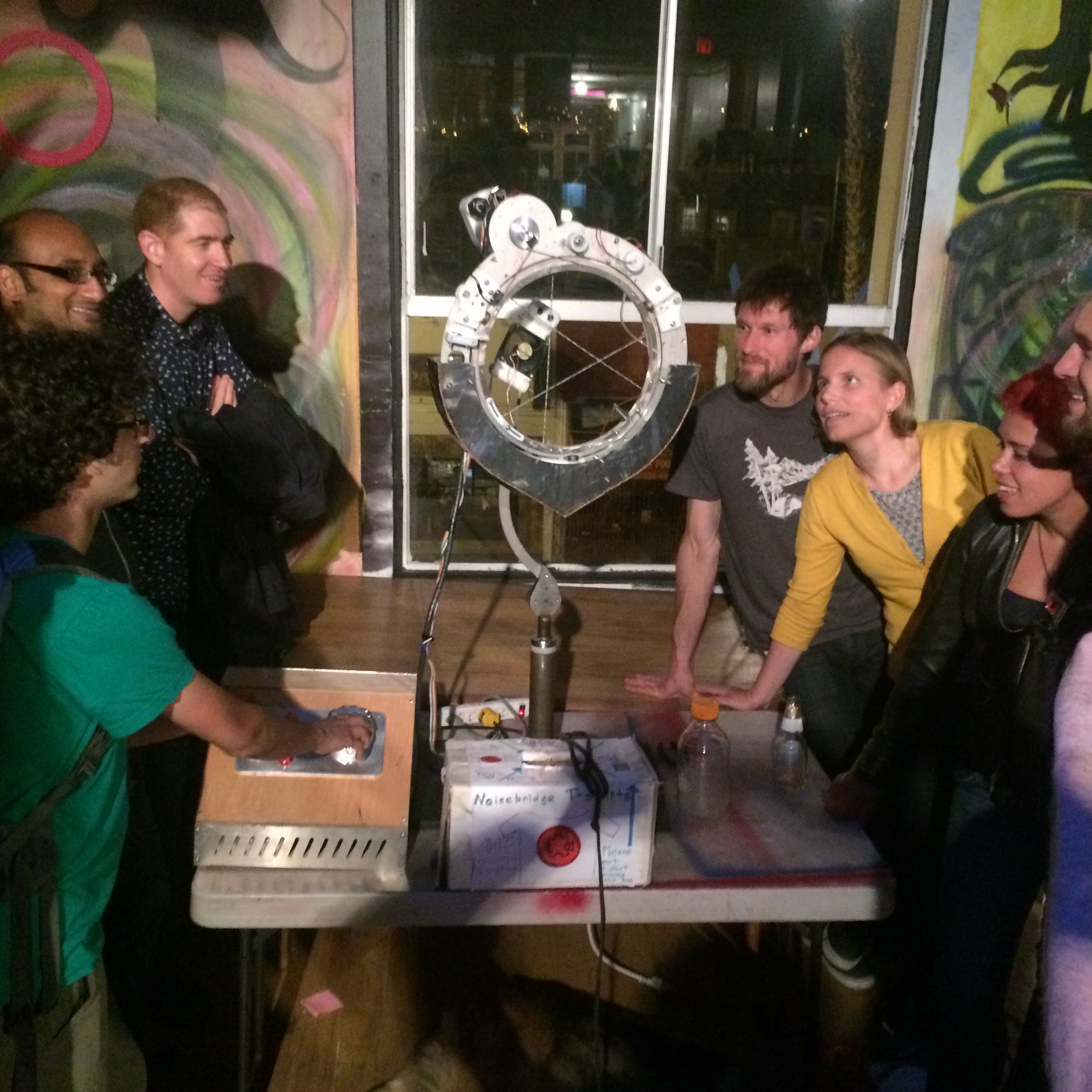
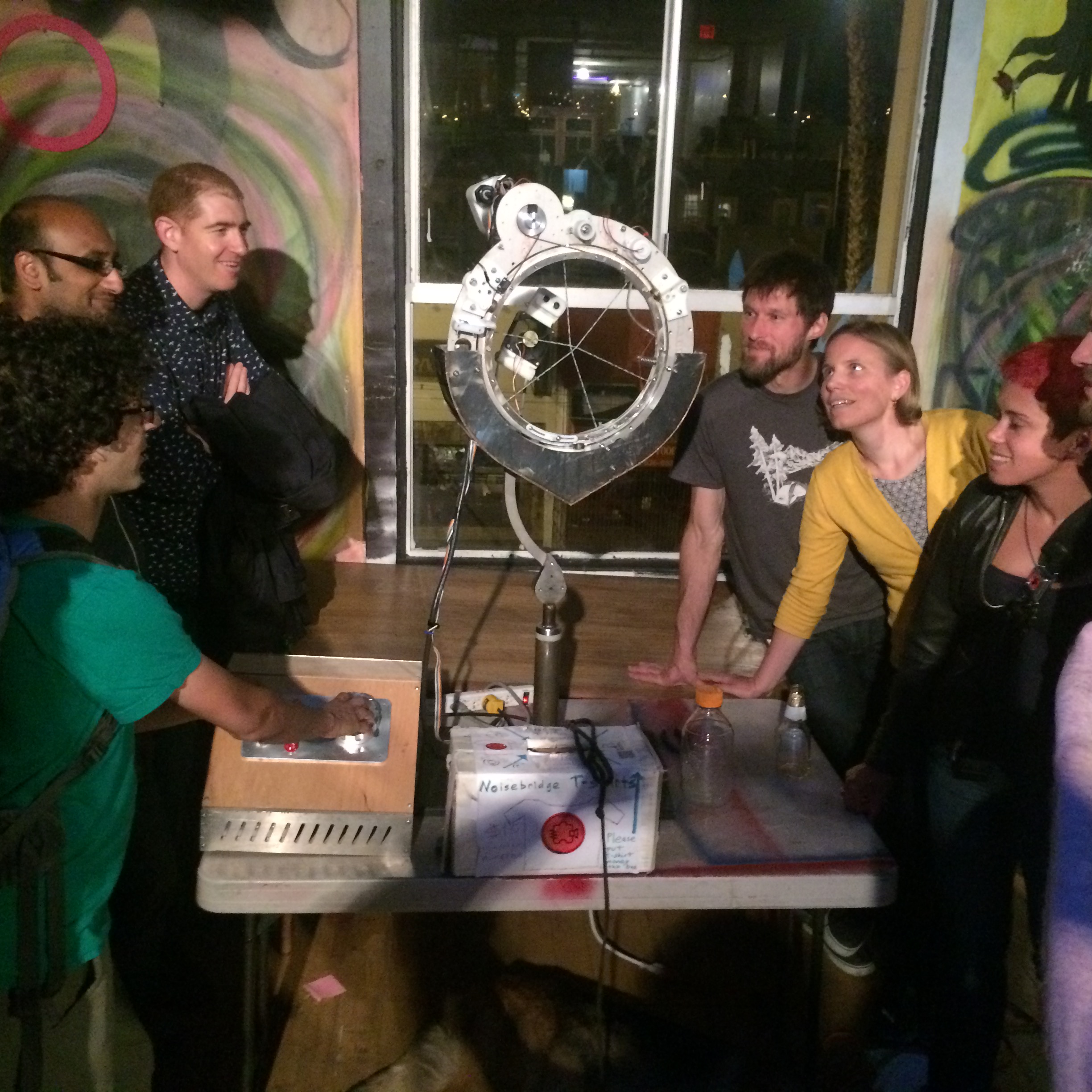
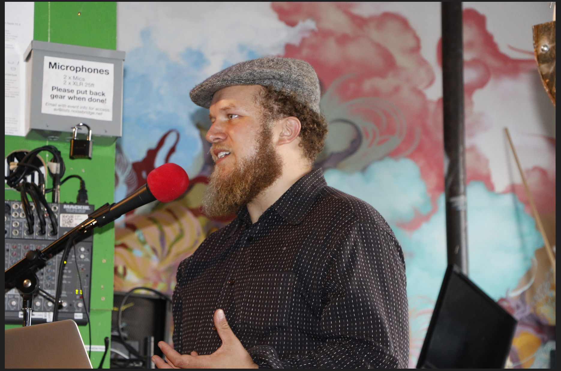
Gordon Kirkwood Presents at historic NoiseBridge Hacker Space for DorkBot SF #82
It was an honor to be invited to present my work to the distinguished audience of DorkBot SF, held at Noisebridge, a storied and significant Hacker space in San Fransico.
![]()
DorkBot is an international speaker series whose self-summary is “People doing strange things with electricity“. In this context I presented some of the more interesting robotic, high voltage photography, and other technical art projects I’ve worked on, especially the recently completed CNC bubble iris.
Fellow presenters included the international director of the Electronic Freedom Foundation, Danny O’Brien, and Jesse Silver, the creator of BlumenLumen, a kinetic origami sculpture featured at Burning Man.


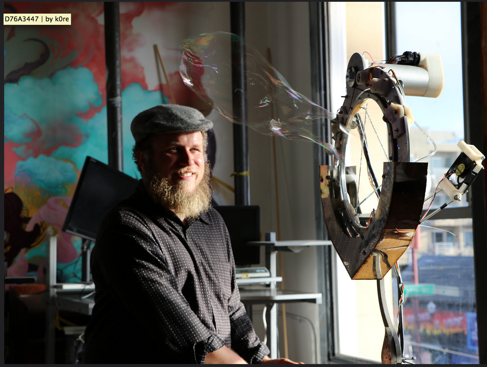
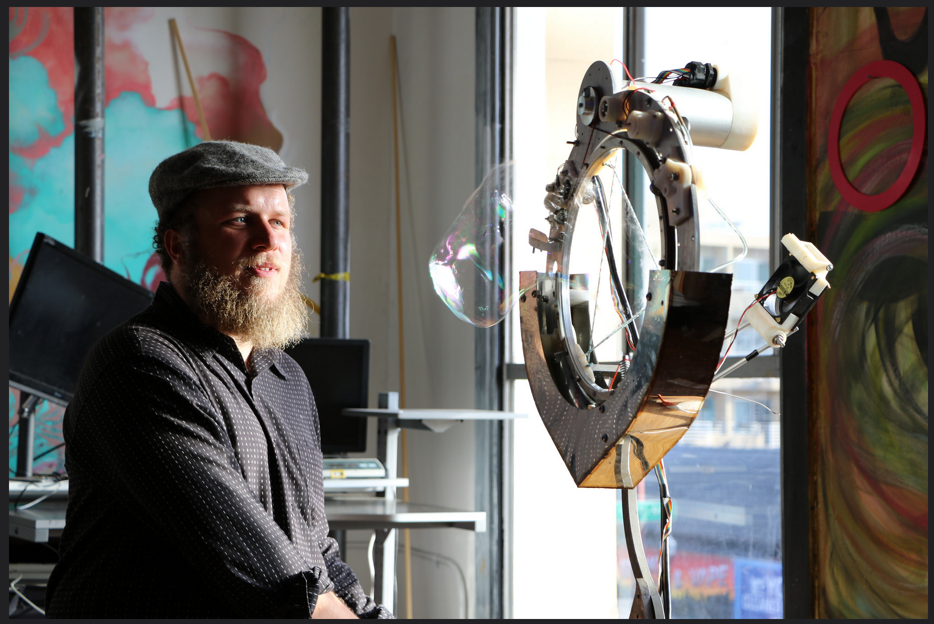
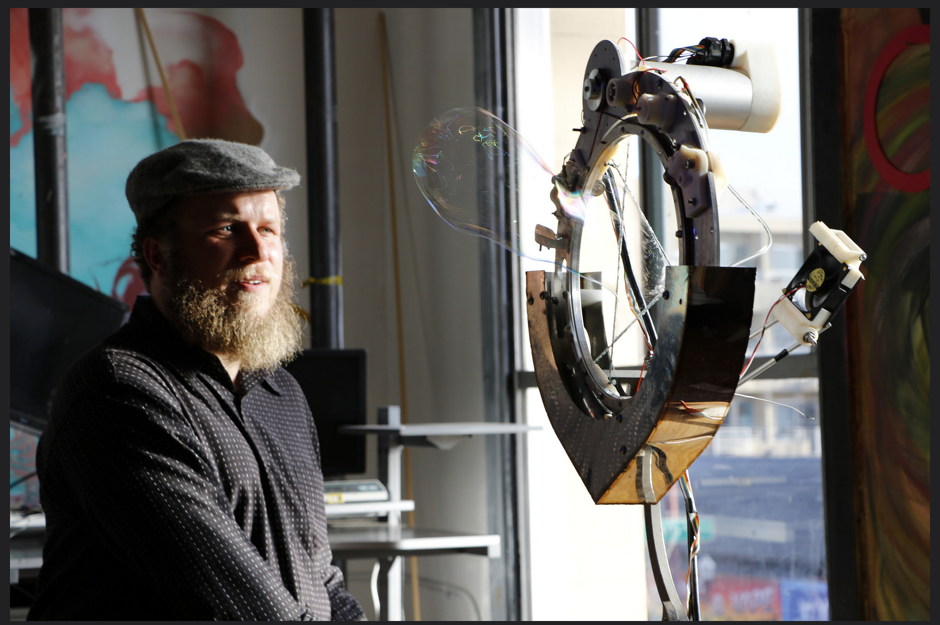
CNC Bubble Iris Article Released
It is a real pleasure to see Make Magazine, Hackaday, and Adafruit #ArtTuesday all re-blog the publication of the apparatus I’ve built to bring new precision, repeatability, and automation to the craft of giant soap bubble making. Stay tuned for all the interesting things I’ll use this instrument for!
- (Make Magazine) Computer Controlled Bubble Blower will Brighten your Day
- (Hackaday) Worlds-greatest-bubble-machine-born-of-space-program
- (Adafruit) Computer Controlled Giant Bubble Machine #ArtTuesday